Insertion loss and return loss or power signal transmitted along a fiber optic link, are generally expressed in dB (decibels) and should always be a positive number. But they can also be negative, which is not good in terms of optical communications but could be useful for other applications.
Let’s clarify the meaning between all of them before going on:
- Return loss measures the amount of light reflected to the source referenced to the amount of light generated at the source and is always a positive number expressed in dB and is expressed by the following equation:
Return loss = 10 * log10 (incident power / reflected power)
- Insertion loss measures the amount of light transmitted through the fiber referenced to the amount of light generated at the source. Generally, high return losses result in low insertion losses. It is expressed by the following equation:
Insertion loss = 10 * log10 (incident power/transmitted power)
For example, a 10 mW signal transmitted through a fiber optic link with 4 dB Insertion loss results in a total transmitted power of 3.98mW.
It is a little bit confusing, isn’t it? But don’t worry, it’s usual even among the most experienced users as it is stated in this article from a qualified optical fiber certifier.
Concerning a fiber optic link, the most common parameter used to measure the performance is insertion loss, since it indicates the amount of signal loss due to connections, attenuation etc. along the link. Insertion loss is a positive number that informs about the amount of signal lost when comparing the input power with the output power. Therefore, the higher the insertion losses the worse the performance of the fiber link. An insertion loss negative value can be generally associated to an incorrect measurement generally caused by dirty connectors or wrong zero reference. However, negative loss, or gains can also occur due to differences between the connected fibers (i.e. the fibers have different backscatter coefficients), which would require complementary measurements of the fiber link in both directions, known as bidirectional test measurements.
The other fiber optic link performance parameter that is most often measured is the return loss. It consists of a measurement of the amount of light injected from the source compared to the amount of light reflected to the source. It is expressed as a positive number in dB and the higher the value, the better the fiber link performance, or in other words, the higher the transmitted power.
If we focus on the transmission medium, we can also find other parameters that give an idea of the properties of the medium or material the light is travelling through. These parameters are known as reflectance, transmittance and absorbance and they measure the amount of light reflected, transmitted or absorbed by a reflective, transmissive or absorptive event (i.e. a connector) respectively compared to the amount of light injected from the source (see Figure below).
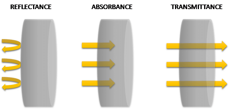
They can be defined as follows:
- Reflectance also measures the amount of reflected light referenced to an initial or reference measurement. Reflectance can be expressed in % or dB and is given as a negative number as it is expressed below:
Reflectance = (reflected power / incident power) * 100
Reflectance = 10 * log10(reflected power / incident power)
- Transmittance measures the amount of light transmitted referenced to an initial or reference measurement (it can be the original light source). It can be given in % or dB as follows:
Transmittance = (transmitted power / incident power) * 100
Transmittance = 10 * log10(transmitted power / incident power)
- Absorbance measures the amount of light absorbed referenced to an initial or reference measurement (it can be the original light source) and is given in dB. It can be considered the opposite measurement of the transmittance expressed in the equation below:
Absorbance = -10 * log10(transmitted power / incident power)
Reflectance, transmittance and absorbance are expressed in dB but can be also expressed in %). When expressed in dB reflectance and transmittance are negative while absorbance is positive as it can be deduced by the equations above.
The later parameter is generally used to extract the concentration of molecular species in a solution, as it is described by Beer-Lambert Law exploited in the fabrication of optical sensors:
A = e[C] l
Where A is the Absorbance, e is the extinction coefficient of the absorbing molecules, [C] is the molar concentration and l is the optical length.
In this sense, care should be taken with the obtained measurements since high absorbance values mean that only a small amount of light can be detected at the output, which can increase considerably the measurement errors, and therefore it is advised not to rely on absorbance measurements above 15-20 dB unless the instrumentation used, light source and detector, guarantees a proper performance (i.e. high power stability in the case of light sources or high signal to noise ratio in the case of the detectors).
Learn more about transmittance, absorbance and their relationship in this post from Abdul Aziz.